
Robotic Polishing for Aerospace Parts: Controlling Surface Finish and Accuracy
author
Achieving a consistent surface finish without compromising dimensional accuracy is a critical challenge in aerospace manufacturing. Robotic polishing for aerospace parts offers a repeatable approach, but its performance depends on factors such as force control, tool wear, material behavior, and measurement reliability. The useful question is not whether a robot can produce a smooth surface once. It is whether the process can do so across the required geometry, throughout the life of the abrasive, without removing material that the part cannot afford to lose.
This distinction also matters to renewable-energy manufacturers working with complex metallic components, including turbine hardware. Some process-control lessons transfer between industries, but acceptance criteria do not automatically transfer with them. An aerospace component may have fatigue, coating, and traceability requirements that are specific to its design and service conditions.
A polished surface is not the same as an accurate part
Surface finish and dimensional accuracy are related, but they are separate outcomes. A polishing pass can reduce roughness while changing a blade profile, rounding an edge, or thinning a local wall. Conversely, a part can remain within its dimensional tolerance and still contain scratches, directional marks, or isolated defects that violate the surface requirement.
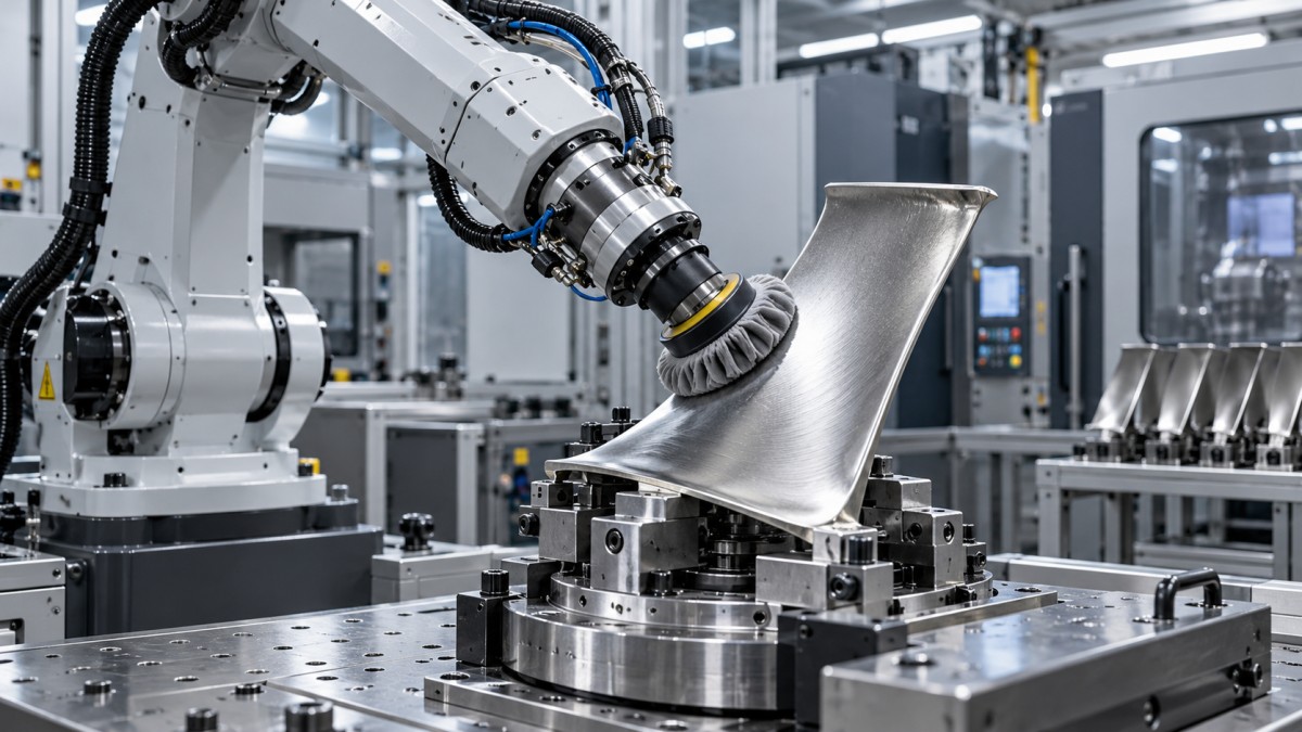
Consider a contoured blade with a narrow edge and a broader airfoil surface. A compliant polishing tool may follow the broad surface comfortably, then make disproportionately concentrated contact as it crosses the edge. If the program uses the same force and feed everywhere, the edge can lose material before the larger surface reaches its required finish. A fixture that flexes under load makes the result harder to predict.
The evaluation therefore starts with the drawing and the approved process requirements: which surfaces may be polished, how much stock is available, which features must be protected, and how the finished geometry will be inspected. A demonstration on a flat coupon is useful for screening abrasives; it is not proof that the same settings will work around fillets, transitions, or thin sections.
Where force control helps—and where it does not
In robotic polishing, the contact force influences how the abrasive engages the surface. Too little contact can leave the incoming texture largely unchanged; too much can accelerate removal, deform the tool, or generate heat. Closed-loop force control can adjust the robot or a compliant end effector as the surface position changes, but a force setpoint alone does not define the process.
The same commanded force can produce different local pressure when the contact patch changes. Tool orientation, pad stiffness, abrasive condition, and surface curvature all affect that patch. On a convex feature, for example, a small contact area may make a seemingly modest force aggressive. In a concave region, poor access may cause the edge of the tool rather than its intended working face to touch the part.
Ask to see force data during entry, steady contact, corners, and exit—not just a single average value. Look for overshoot when contact begins and disturbances when the tool changes direction. The sensor’s calibration, location, filtering, and compensation for tool weight and motion also matter: a stable-looking trace is not necessarily an accurate measurement of the force at the contact point.
A low-force approach is not automatically safer. If the tool spends too long on a small region to achieve the finish, local removal or heating can still become a problem. Force, traverse speed, spindle speed, pass overlap, and dwell time need to be assessed together.
Toolpath quality depends on the part actually in the fixture
An offline path generated from nominal CAD geometry can be a good starting point. It becomes less reliable when incoming parts vary, the fixture locates them differently, or the robot’s effective tool center point changes after a consumable replacement. Force compliance can accommodate some position error, but it cannot correct every orientation error or guarantee that the right area receives the right dwell.
For complex parts, evaluators should understand how the system establishes the relationship between the robot, fixture, tool, and workpiece. Does it rely on a fixed setup, probe known features, or use a scan to register each part? Registration adds time and its own measurement uncertainty, but it may be worthwhile when part variation is large relative to the available polishing allowance.
Pay particular attention to path boundaries. Pass overlap that is adequate on an open surface can produce a ridge or excessive removal near a boundary. Restricted access can also create unpolished strips that look acceptable from one viewing angle. A practical trial should include the awkward features, not just the easiest region of the component.
Abrasive wear is a process variable, not a maintenance detail
A fresh abrasive and a worn one can behave differently even when the robot repeats the same path and force. Loading, glazing, pad deformation, and abrasive breakdown can change both removal rate and the resulting texture. On some materials, contamination carried over from another operation is also a concern.
A supplier should be able to explain how consumable life is determined: by elapsed time, number of parts, measured performance, or another controlled criterion. A fixed replacement interval is straightforward, but it is only convincing if the evidence includes parts made near the end of that interval. Testing exclusively with new pads leaves a gap in the qualification.
Material behavior deserves the same attention. Nickel-based alloys, titanium alloys, aluminum alloys, and coated surfaces do not necessarily respond alike to an abrasive sequence. Heat sensitivity, work hardening, loading, and contamination risks depend on the material and operation. Where a coating or surface treatment is present, confirm whether polishing is permitted at all and whether the specified inspection can detect unacceptable coating removal.
What to measure before accepting a result
A single roughness value is rarely a complete acceptance argument. Ra is widely used, but it is an average and can obscure isolated scratches or peaks. Other parameters may be specified by the drawing or process documentation; the evaluator should not substitute one parameter for another simply because an instrument reports it conveniently.
Measurement conditions matter as well. Record the instrument type, calibration status, sampling and evaluation settings, measurement direction, and locations. A stylus measurement taken across polishing marks can differ from one taken along them. Optical methods can be useful on difficult geometries, but their suitability depends on surface reflectivity, access, and the instrument’s validated capability. Compare results using the method required by the applicable specification, not whichever method gives the most attractive number.
Surface texture standards can help establish a common language. ISO 21920 addresses profile surface texture, while ISO 25178 addresses areal surface texture. Their relevance depends on what the drawing and contractual requirements call up, including the applicable editions and measurement conditions. Neither series, by itself, certifies that a polishing process is acceptable for a particular aerospace part.
Dimensional inspection should be planned alongside finish inspection. Depending on the feature, this may involve a coordinate measuring machine, a suitable optical system, dedicated gauges, or another approved method. Compare pre- and post-process geometry where feasible, especially at edges and thin sections. The measurement uncertainty must be small enough to support a decision against the tolerance; otherwise, an apparent pass may say more about the measurement system than the process.
Surface integrity may require additional attention where the part specification calls for it. A smooth finish does not, on its own, establish the absence of unacceptable thermal damage, embedded abrasive, or other subsurface effects. The required checks belong to the part’s engineering and quality documentation, not to a generic polishing checklist.
Design a trial that exposes variation
A useful acceptance trial should represent the intended production conditions: incoming surface condition, material, geometry, fixture, consumables, and inspection method. If the actual component is too costly for early development, representative coupons and test pieces can reduce risk, but the final assessment still needs to address the production geometry.
Define the locations to be measured before seeing the results. Include difficult transitions, edges, accessible broad surfaces, and any region where the tool changes direction. Evaluate multiple parts where practical, with fresh and near-end-of-life consumables, and document setup changes. Report individual results and locations, not just an overall average. A repeatable failure is still a failure; a repeatable pass needs to include the conditions under which it was achieved.
Also separate robot repeatability from process capability. A robot may return to a programmed position consistently while part location, abrasive wear, or contact conditions vary enough to affect the finished surface. Capability calculations can be useful when the data and sampling plan support them, but they should not replace an investigation of outliers or defects hidden between measurement points.
Standards, traceability, and the renewable-energy connection
For aerospace work, the governing requirements may include customer specifications, drawing notes, approved manufacturing instructions, and quality-management obligations. AS9100 is an aerospace quality-management standard; it is not a surface-finish specification and does not by itself approve a particular polishing recipe. Check the contract for the required standard, revision, supplier approvals, and any restrictions on process changes or subcontracting.
The evidence package should connect each inspected part to its incoming condition, program revision, fixture, consumable batch or identity where required, inspection records, and any rework. If the abrasive, force strategy, or measurement method changes after approval, the organization must determine whether the change requires customer notification or requalification under the applicable agreement.
Renewable-energy applications offer a useful comparison, particularly where turbine components have complex surfaces and expensive rework. The same questions about contact, wear, and measurement apply. However, component size, production volumes, environmental exposure, and acceptance criteria may be different enough to change the preferred process. A result from a wind-energy part should not be presented as aerospace validation without a relevant assessment against aerospace requirements.
NexusHome Intelligence emphasizes the same evidence-led distinction in its work on connected energy and hardware systems: a performance claim is only useful when the test conditions and measurements can be examined. For a polishing cell, that principle means asking for the actual force traces, surface maps, dimensional records, consumable history, and applicable acceptance criteria. If those records are missing, a good-looking sample is a starting point for a trial—not evidence that the process is ready for release.
Protocol_Architect
Dr. Thorne is a leading architect in IoT mesh protocols with 15+ years at NexusHome Intelligence. His research specializes in high-availability systems and sub-GHz propagation modeling.
Related Recommendations
- Dr. Aris ThorneRobotic Polishing for Aerospace Parts: Controlling Surface Finish and Accuracy
- Dr. Aris ThorneST Launches MatterConnect to Simplify Smart Home Device Credential Provisioning
- Dr. Aris ThorneRobot Arm Ingress Testing: Verifying IP Ratings for Solar Cleaning
- Dr. Aris ThorneUgreen Delays HomeAgent Again to Refine Matter Support and Local AI
- Dr. Aris ThorneMatter 1.6.1 Reaches First Platforms as Open-Source SDK Adds Full Support
- Dr. Aris ThorneHow to verify Matter certification for solar-aware smart plugs
- Dr. Aris ThorneHow to Build a Voice-Enabled Smart Home Ecosystem That Works Across Brands
- Dr. Aris ThorneHow to Choose a Jewelry Pliers Set for Precision Wirework and Small Repairs
- Dr. Aris ThorneSupplier Capability Criteria for Renewable Energy Projects: A Procurement Checklist
- Dr. Aris ThorneCustom Printed Lanyards for Renewable Energy Sites: What Buyers Should Specify
Analyst